dsPIC 30F3010 : Introduction


Cette page presente une introduction à l'utilisation du microcontroleur dspic 30F3010 de Microchip.
Elle comporte des schémas electroniques ainsi que des programmes en C.

Executable and sources sont fournis.

Voir également la page des projets sur dspic.

Introduction :

Dans les systèmes de commande, on a souvent une boucle de régulation :

Exemple d'une boucle de régulation

On s'intéresse ici à l'organe de commande qui a aussi pour mission de traiter la mesure, de calculer puis de sortir les ordres de commande (signaux MLI dans le cas de l'onduleur).
Nous avons choisis un microcontrôleur 16 bits récent et qui permet une prise en main rapide de sa programmation et utilisation.
De plus, le coût des outils de développement est réduit :
Cela permet d'utiliser ce microcontrôleur pour d'autres projets (personnels). Il se rapproche beaucoup du PIC 16F84 ou autres qui sont des microcontrôleurs 8 bits et pour lesquels les schémas sont innombrables sur Internet, mais il offre en plus, par rapport à cette ancienne génération :
un cœur DSP (Digital Signal Processeur), qui, même s'il est modeste, permet de faire des calculs relativement lourds, mais surtout la possibilité de debugger le programme à l'aide de l'interface ICD2 (une broche à 5 contacts : Figure 1).

Les schémas qui vont suivre correspondent aux maquettes de TP réalisées pour les besoins du cours.


Figure 1 : Brochage d'interface ICD2

Choix du dspic 30F3010 :

L'intéret de ce dsPIC 30F3010 est que c'est un microcontrôleur 16 bits de chez Microchip, il comporte une interface de communication Série mais aussi des sorties PWM, des entrées ADC (10 bits). Il a un petit noyeau DSP (multiplication) d'où le nom dsPIC par rapport aux PIC bien connus.

Caractéristiques du dsPIC 30F3010

Comme il a 28 pattes (pins) et qu'il existe en boitier DIP, il peut être facilement utilisé pour des petits projets d'électroniciens amateurs.
On le programme en assembleur ou en C. Nous avons choisi le language C à cause de son universalité et la facilité d'adaptation des algorithmes que nous avons déjà développé (pilotage de LCD, commande V/f) pour le DSP TMS 320F240.

La datasheet 70141c du dsPIC 30F3010 renseigne sur la connectique et les registres que l'on utilise pour le programmer.
Il vaut mieux regarder la documentation plus complete de toute la famille dsPIC (70046E).

Connexions du dsPIC 30F3010

Chapitres :

Tout d'abord examinons les différentes interfaces que nous utiliserons :

Documents :

(70141c) Datasheet du dsPIC 30F3010.
(70046E) Documentation plus complete sur les fonctionnalités de la famille dsPIC.
(70043F) Comparaison et brochage des dsPIC de la famille 30Fxxxx.

Les projets présentés :

Sur le lien, nous présentons plusieurs projets d'initiation et des applications (commande de moteur linaire (MRV et MS), transmetteur X10 RF, gestion de thermocouple et transmission RF à 2.4 GHz, pilotage d'écran LCD graphique (Nokia 3310), commande V/f.

  • Projets de moteurs linéaires : MRVlin (moteur à réluctance variable linéaire) et MSlin (moteur synchrone linéaire).

    MRVlin version capteur infrarouge MSlin état des sondes Hall


    I/O :

    Configuration et exploitation des ports d'entrées sorties logiques (E/S ou I/O).

    Le dsPIC comporte 20 pins d'entrées sorties partagées. Il faut donc choisir celles qui vont rester sur les fonctions primaires (ADC, SPI, PWM...) et celles qui seront en fonctionnement I/O logique.
    Ce dsPIC comporte plusieurs ports (Port B, C, D, E, et F). Pour chacun, 3 registres sont associés (TRISx, PRTx, LATx).
    Exemple d'utilisation pour allumer une diode LED :
       
    #define LEDBlue PORTEbits.RE0      // donne un nom explicite au bit n°0 du port E
    TRISE = 0xFFFE;  // définit la direction des ports : RE0 Output LED, RE1 à RE8 input

    PORTEbits.RE0=1;
    // ligne équivalente à
    LEDBlue=1;        // met le bit à 1 donc VDD (5V ou 3V) sur la pin RE0


    Exemple de lecture du port d'entrée touche:
       

    #define ToucheRUN PORTEbits.RE1    // donne un nom explicite au bit n°1 du port E
    #define LEDBlue PORTEbits.RE0      // donne un nom explicite au bit n°0 du port E
    TRISE = 0xFFFE;  // définit la direction des ports : RE0 Output LED, RE1 à RE8 input
    if (ToucheRUN)  LEDBlue=1;        // Allume la LED si la touche est appuyée
    // ligne équivalente à
    if (PORTEbits.RE1)  PORTEbits.RE0=1;        // Allume la LED si la touche est appuyée

    Attention cependant si l'on écrit 2 fois de suite sur des ports voisins exemple RG0 et RG1.
    Si on le fait de cette manière :
       

      PORTGbits.RG0 = 1;
      PORTGbits.RG1 = 0;
     
    et en fonction de l'état initial des ports, on peut avoir des résultats très bizarres dûs au Latch... voir doc.
    Donc il vaut mieux utiliser :
       

      LATGbits.LATG0 = 1;
      LATGbits.LATG1 = 0;
     
    Pour la lecture du ports (Input), il vaut mieux utiliser
       
    Etatreel = PORTGbits.RG2
    car on aura l'état réel de la broche du dspic.


    ADC :

    Configuration et exploitation du convertisseur analogique numérique 10 bits.
    L'ADC permet de convertir une grandeur continue analogique de tension comprise entre AVSS et AVDD (0 à 5V ou 3V).
    Il existe 2 manières de lancer la conversion (SOC : Start Of Conversion) :
    Lancer manuellement la conversion ou de manière automatique sur un évènement (Timer, PWM...).
  • Configururation de l'ADC pour lancer une conversion immédiate.
       

      // config ADC en lancement immédiat
      ADCON1 = 0x800                      C;        //Conv continously, 4 ch simultanés, ADC Off for configuring
      ADCON2 = 0x0200;  // simulataneous sample 4 channels
      ADCHS = 0x0022;        // Connect RB2/AN2 as CH0 = pot K_V_f  AN3/RB3 to CH1 = pot Fs
      ADCON3 = 0x0080;      // Tad = internal RC (4uS)
      ADCON1bits.ADON = 1// turn ADC ON
    //...
      ADCON1bits.SAMP = 0;    // start conversion
      while(!ADCON1bits.DONE) {}  // attend la fin
      CMPR=ADCBUF0;


  • Lancement automatique de la conversion au milieu du motif PWM, puis le système appelle notre ISR (Routine de Service d'Interruption) _ADCInterrupt :
       

    void InitADC10(void)
    {
      ADPCFG = 0xFFC3;        // all PORTB = Digital(1) ;RB2 to RB5 = analog(0)  ie 1100 0011
      ADCON1 = 0x006F;        // PWM starts conversion, 4 ch simultanés, ADC Off for configuring
      ADCON2 = 0x0200;        // simulataneous sample 4 channels, ADC INTerrupt à chaque EOC=100 us
      ADCHS = 0x0022;          // AN2/RB2 Ch0 Vref, AN3/RB3 Ch1 Vmes, AN4/RB4 Ch2 Vreflimiteur, AN5/RB5 Ch3 NC
      ADCON3 = 0x0080;        // Tad = internal RC (4uS)
      IFS0bits.ADIF = 0;      // Adc int flag Off
      IEC0bits.ADIE = 1;      // Adc int On
      ADCON1bits.ADON = 1;    // turn ADC ON
    }
    //---------------------------------------------------------------------
    // The ADC interrupt reads the demand pot value.
    // tt est synchrone % à cette int de ADC int =2*PWMperiod=2*62.5 us=125 us
    //---------------------------------------------------------------------
    void __attribute__((__interrupt__)) _ADCInterrupt (void)
    {
    InterruptLED=1// pour visualiser sur oscillo le tps d exécution de la routine
      IFS0bits.ADIF = 0
      Vref=ADCBUF0;    // 0 à 1023 ie 0 à 0x3FF
      Vmes=ADCBUF1;
      Vreflimiteur=ADCBUF2;  
    //....
    InterruptLED=0
    }
    //------------------------------------------------------------------------


    PWM :

    Configuration et exploitation des signaux à modulation de largeur d'impulsion (MLI ou PWM).
    Le module PWM du dsPIC permet de générer des signaux de commande de transistors de puissance (en 0-5V ou 0-3V).
    Ces signaux peuvent être directement utilisés pour attaquer des circuits onduleur triphasés commme le (L6234) ou des hacheurs (L298)...
    Ceci se fait en interne par comparaison de la référence avec un timer qui compte (et décompte).

    Expliquer : les registres (PTPER, IE, IF, OVDCON, PWMCON1, PTCON, PDC1, PDC3, PDC3), HalfDuty, FullDuty, interruptions,
       

    //Configuration bits
    // Q=7.3728 MHz
    _FOSC(CSW_FSCM_OFF & XT_PLL16)// 7.3728MHz *16 = 117.9648 MHz /4 = 29.4912 MIPS maxi pour ce pic
    _FWDT(WDT_OFF);
    _FBORPOR(PBOR_OFF & BORV_27 & PWRT_16 & MCLR_EN);
    _FGS(CODE_PROT_OFF);
    //-----------------------------------------------------------------------------
    // Program Specific Constants
    #define FCY 29491200          // Instruction cycle rate (Osc x PLL / 4)
    #define FPWM 16000            // PWM freq
    #define HalfDUTY  921  // set the pwm half duty = PTPER = 920.6 =FCY/FPWM/2-1;
    #define FullDUTY HalfDUTY*2   //  car PDCx a une double resolution % PTPER
    #define MILLISEC FCY/29491      // 1 mSec delay constant


    #define DS_PoszReg 100      // Compteur pour la regulation 100* 125us = 12.5 ms

    #define InterruptLED  LATBbits.LATB0      // Output
    #define InfoLED    PORTBbits.RB1      // Output
    #define RunningLED  LATDbits.LATD1        // Output
    #define StartRegul  PORTDbits.RD0    // Input   // BP2 pour commencer StartRegul
    // Enable surles PWM low
    #define L298_p_Enable PORTEbits.RE0        // la pin PWM1 low utilisé en Enable du L298
    #define L298_alpha_Enable PORTEbits.RE2    // la pin PWM2 low !  
    #define L298_beta_Enable  PORTEbits.RE4  // la pin PWM3 low !
    // l inhib PWM se fait aussi par cavalier sur la carte

    //-----------------------------------------------------------------------------
    //  Setup ports
    //-----------------------------------------------------------------------------
    void setup_ports(void)
    {
      // Clear All Ports Prior to defining I/O
      PORTB=0//Initialize LED pin data to off state
      PORTC=0;
      PORTD=0;
      PORTE=0
      // Now set pin direction registers
      TRISB = 0xFFFC;  // RB0 interruptLED, RB1 InfoLED output,   RB2-5 inputs : ADC RB2-5
      TRISC = 0xDFFF;  // U1ATX/RC13 in , U1ATX/RC14 out
      TRISD = 0xFFFD;  //  RunningLED RD1  Output , StartPrg RD0 Input
      TRISE = 0x01C0;  // RE1, RE3, RE5 are the PWMs -> outputs les low : RE4, RE2, RE0 : L298 Enable output, RE8 input
      TRISF = 0xFFFF;  // RF NC input
    }
    //-----------------------------------------------------------------------------
    //  Setup the ADC registers for :
    //  4 channels conversion
    //  PWM trigger starts conversion
    //  AD interrupt is set and buffer is read in the interrupt
    //-----------------------------------------------------------------------------
    void InitADC10(void)
    {
      ADPCFG = 0xFFC3;        // all PORTB = Digital(1) ;RB2 to RB5 = analog(0)  ie 1100 0011
      ADCON1 = 0x006F;        // PWM starts conversion, 4 ch simultanés, ADC Off for configuring
      ADCON2 = 0x0200;        // simulataneous sample 4 channels, ADC INTerrupt à chaque EOC=100 us
      ADCHS = 0x0022;          // AN2/RB2 Ch0 Bref, AN3/RB3 Ch1 Bmes, AN4/RB4 Ch2 NC, AN5/RB5 Ch3 NC
      ADCON3 = 0x0080;        // Tad = internal RC (4uS)
      IFS0bits.ADIF = 0;      // Adc int flag Off
      IEC0bits.ADIE = 1;      // Adc int On
      ADCON1bits.ADON = 1;    // turn ADC ON
    }
    //-----------------------------------------------------------------------------
    //  InitMCPWM, intializes the PWM as follows:
    //  FPWM = 16 khz voir en haut
    //  Independant PWMs
    //  Set ADC to be triggered by PWM special trigger
    //-----------------------------------------------------------------------------
    void InitMCPWM(void)
    {
      PTPER = HalfDUTY;  // set the pwm period register, ne pas oublier la double précision
      PWMCON1 = 0x0770;  // enable PWMs tt le tps
      PDC1=HalfDUTY; PDC2=HalfDUTY; PDC3=HalfDUTY;      // init sans rien, apres une regul ça change
      L298_p_Enable=0;            // disable L298 principal
      L298_alpha_Enable=0;        // disable L298 alpha
      L298_beta_Enable=0;     // disable L298 beta
      OVDCON = 0xFFFF;  // Cmde MLI, no effect of OVDCON
      SEVTCMP = PTPER;    // set ADC to trigeer at ...
      PWMCON2 = 0x0000;  // 1 PWM values
      PTCON = 0x8002;   // start PWM symetrique
    }
    //---------------------------------------------------------------------
    //  The ADC interrupt reads the demand pot value.
    // tt est synchrone % à cette int de ADC int =2*PWMperiod=2*62.5 us=125 us
    //---------------------------------------------------------------------
    void __attribute__((__interrupt__)) _ADCInterrupt (void)
    {
      InterruptLED=1
    // InfoLED=1;
      IFS0bits.ADIF = 0
      Bref=ADCBUF0;    // max 1023
      Bmes=ADCBUF1;
      Vreflimiteur=ADCBUF2;  
      fs=(ADCBUF3-512)<<3;    // 4.12 pu 4096=1.0=20 Hz
      if (Vreflimiteur>HalfDUTY)  Vreflimiteur=HalfDUTY;  // jusquà 624
      Vrefmax=FullDUTY-Vreflimiteur;    // si RefI=0 alors pleine puissance autorisée
      Vrefmin=Vreflimiteur;

    // reg PI
    // exécute toutes les DS_PoszReg (100) * fois
      if ( ++countReg==DS_PoszReg )
        {
        countReg=0;
        // regul angle
        e=Bref-Bmes;    // erreur à forcer à zéro
        Vref =Kp_reg*e + xe_reg + Kd_reg*(e-Olde) + HalfDUTY;
    //  if ( Vref>Vrefmin && Vref<Vrefmax )  xe_reg += Ki_reg*e;
        xe_reg += Ki_reg*e;
        if (xe_reg<-FullDUTY)  xe_reg=-FullDUTY;
        if (xe_reg>FullDUTY)    xe_reg=FullDUTY;
        if (Vref<Vrefmin) Vref=Vrefmin;
        if (Vref>Vrefmax) Vref=Vrefmax;
        Olde=e;
        // mise à jour du rapport cyclique
        PDC1=Vref;      // bobine principale
        }
      // tensions pour faire tourner, s exécute tte les ADC int =2*PWMperiod=2*62.5 us=125 us
      thetasinc=__builtin_mulss(Ktheta,fs)>>12;
      thetas+=thetasinc;
      sinthetas=SinusTable[thetas>>8];
      costhetas=SinusTable[((thetas>>8)+64) & 255];
    // debug
      Vds=Vrefmax;
      Valphas=__builtin_mulss(Vds,costhetas)>>12;
      Vbetas =__builtin_mulss(Vds,sinthetas)>>12;
      tmp1=+(__builtin_mulss(ByEs2,Valphas))>>12;
      PDC2=HalfDUTY+tmp1;
      tmp1=(__builtin_mulss(ByEs2,Vbetas))>>12;
      PDC3=HalfDUTY+tmp1;
      // debug
      PDC2=HalfDUTY;  // bobine alpha
      PDC3=HalfDUTY;  // bobine beta

    // communication dsPIC -> PC
      if (!--SeqComm)  {
                        SeqComm=SeqCommMax;
                        Flags.SendData=1;
                        }
    InterruptLED=0
    }
    //------------------------------------------------------------------------


    Timer :

    Configuration et exploitation des Timers.
       

    #include "p30F3010.h"

    //Configuration bits
    /// Qartz de 10 MHz
    _FOSC(CSW_FSCM_OFF & XT_PLL8)//10Mhz *8 = 80 MHz /4 = 20 MIPS maxi pour ce pic
    _FWDT(WDT_OFF);
    _FBORPOR(PBOR_OFF & BORV_27 & PWRT_16 & MCLR_EN);
    _FGS(CODE_PROT_OFF);
    //-----------------------------------------------------------------------------
    //Program Specific Constants
    #define FCY 20000000          //Instruction cycle rate (Osc x PLL / 4) = 20 MIPS
    #define T1Period 4000     // pour 200us à 20 MHz = T1Period = 4000=FCY*200us
    #define tcntPRD 500     // combien de fois pour ariver en Te=0.1s avec des pas de 200us : 500

    //-----------------------------------------------------------------------------
    //  intitialise timer 1 et l interruption
    //-----------------------------------------------------------------------------
    void initTimer(void)
    {
    // Timer1 pour l ISR des 100 us
      T1CON = 0;          // ensure Timer 1 is in reset state, internal timer clock Fosc/4, no prescale
      TMR1  = 0;          // RAZ Timer1
      IFS0bits.T1IF = 0// reset Timer 1 interrupt flag
      IPC0bits.T1IP = 4// set Timer1 interrupt priority level to 4
      IEC0bits.T1IE = 1// enable Timer 1 interrupt
      PR1 = T1Period;   // set Timer 1 period register
      T1CONbits.TON = 1// enable Timer 1 and start the count
    }

    //-----------------------------------------------------------------------------
    // Timer1 interrupt fait le calcul et l allumage des LED
    // ISR toutes les 200 us
    //---------------------------------------------------------------------
    void __attribute__((__interrupt__)) _T1Interrupt( void )
    {
      IFS0bits.T1IF = 0

      if (++tcnt>=tcntPRD) 
                {// ici on est toutes les secondes
                tcnt=0;
                TimeStamp++;
                if (++Sec==60)
                      {
                      Sec=0;
                      if (++Min==60)
                            {
                            Min=0;
                            if (++Hour==24) Hour=0
                            }
                      }
                sprintf(LCDbuffer, "Il est :");
                LCD3310_GotoXY(0,1);
                LCD3310_SendMsg(LCDbuffer);
                sprintf(LCDbuffer, "%02d:%02d:%02d",Hour, Min, Sec);
                LCD3310_GotoXY(0,2);
                LCD3310_SendMsg(LCDbuffer);
                }
    }
    //-----------------------------------------------------------------------------


    UART :

    Interface série asynchrone.
       

    // RS232 -------------------------------------------
    unsigned char *TXPtr;
    unsigned char *RXPtr;
    void InitUART(void);
    void SendMsg(void);
    #define CR  0x0D
    #define LF  0x0A
    #define BAUD 19200
    #define OffsetTimeStamp 10        // offset in OutData : position de la val de TimeStamp
    unsigned char InData[] = {"000000"};
    unsigned char OutData[] = {"TimeStamp=0000 Ssr0_T=0000\r\n"};
    int SeqComm;    // ttes les 0.5 s
    #define SeqCommMax 5000


    //---------------------------------------------------------------------
    // Below are the interrupt vectors for the serial receive and transmit
    //--------------------------------------------------------------------- 
    void __attribute__((__interrupt__)) _U1TXInterrupt(void)
    {
      IFS0bits.U1TXIF = 0// clear interrupt flag
    }
    //---------------------------------------------------------------------
    void __attribute__((__interrupt__)) _U1RXInterrupt(void)
    {
      IFS0bits.U1RXIF = 0// clear interrupt flag
      *RXPtr = U1RXREG;
      if (*RXPtr == CR)
        {Flags.CheckRX = 1;
        RXPtr = &InData[0];}
      else *RXPtr++;
    }
    //------------------------------------------------------------------------
    //  Transmission over serial
    void InitUART(void)
    {
    // Initialize the UART1 for BAUD = 19,200 
      U1MODE = 0x8400;  // enable + alternate pins
    //  U1MODE = 0x8000;  // enable + normal pins
      U1STA = 0x0000;
      U1BRG = ((FCY/16)/BAUD) - 1// set baud to 19200
      IEC0bits.U1RXIE = 1;      // enable RX interrupt
      RXPtr = &InData[0];  // point to first char in receive buffer
      Flags.CheckRX = 0;      // clear rx and tx flags
      Flags.SendTX = 0;
      Flags.SendData = 0;  // clear flag
      SeqComm=SeqCommMax;
      U1STAbits.UTXEN = 1;           // Initiate transmission
    }
    //----------------------------------------------------
    // Convertit un "Word" hexa en "4 chars Hexadécimaux"
    // et les sort sur la table en memoire
    //----------------------------------------------------
    inline void ConvHexa(int Var, int tablePos, unsigned char * table)
    { 
    int tmp;
          tmp=Var & 0x000F;
          if (tmp<=9)  tmp+=0x30;
              else      tmp+=0x37;
          table[tablePos+3]=tmp;

          tmp=Var>>4 & 0x000F;
          if (tmp<=9)  tmp+=0x30;
              else      tmp+=0x37;
          table[tablePos+2]=tmp;

          tmp=Var>>8 & 0x000F;
          if (tmp<=9)  tmp+=0x30;
              else      tmp+=0x37;
          table[tablePos+1]=tmp;

          tmp=Var>>12 & 0x000F;
          if (tmp<=9)  tmp+=0x30;
              else      tmp+=0x37;
          table[tablePos]=tmp;
    }
    //----------------------------------------------------
    // Convertit un "12 bits" en "4 chars décimaux. 2 chars" xxxx.xx
    // maximum : 1023.75 pour 12 bits
    // et les sort sur la table en memoire
    //----------------------------------------------------
    inline void ConvDec(int Var, int tablePos, unsigned char * table)
    { 
    unsigned int k;
    unsigned char c;
    // Char
      k = Var>>2;
      c = k/1000;
      if (c > 0)
        k = k - c*1000;
      table[tablePos]  =(c + 0x30);
      c = k/100;
      if (c > 0)
        k = k - c*100;
      table[tablePos+1]=(c + 0x30);
      c = k/10;
      if (c > 0)
        k = k - c*10;
      table[tablePos+2]=(c + 0x30);
      table[tablePos+3]=(char)(k + 0x30);
      // apres la virgule :
      switch (Var & 0x03)
        {
        case 0 :  table[tablePos+5]=0x30;  // xxxx.00
                  table[tablePos+6]=0x30; break;
        case 1 :  table[tablePos+5]=0x32;  // xxxx.25
                  table[tablePos+6]=0x35; break;
        case 2 :  table[tablePos+5]=0x35;  // xxxx.50
                  table[tablePos+6]=0x30; break;
        case 3 :  table[tablePos+5]=0x37;  // xxxx.75
                  table[tablePos+6]=0x35; break;
        }
    }
    //-----------------------------------------------------------------------------
    void SendMsg(void)
    {
    while (*TXPtr)
      {
      while (U1STAbits.UTXBF);
      U1TXREG = *TXPtr++;
      }
    }
    //------------------------------------------------------------------------
    // SendData sends the debug information on the uart at 19200 baud
    void SendData()
    {
    // Codage ASCII de la donnée hexa
      ConvHexa( TimeStamp, OffsetTimeStamp, OutData);    // TimeStamp en Hexa

    //  Sensor0_Tr=(Sensor0_T >> 3) & 0xFFF;
    //  ConvDec( Sensor0_Tr, OffsetSensor0_Tr, OutData);        // Sensor0_T en Hexa

      TXPtr = &OutData[0];
      SendMsg();
    }
    //------------------------------------------------------------------------


    //-----------------------------------------------------------------------------
    // Timer1 interrupt fait le calcul et l allumage des LED
    // ISR toutes les 200 us
    //---------------------------------------------------------------------
    void __attribute__((__interrupt__)) _T1Interrupt( void )
    {
      IFS0bits.T1IF = 0
    ...
    ...
    ...
    // communication dsPIC -> PC
      if (!--SeqComm)  {
                        SeqComm=SeqCommMax;
                        Flags.SendData=1;
                        }

    }


    //Main routine
    int main(void)
    {
    unsigned int j;
      setup_ports();
      InitVar();
      InitUART();
      initTimer();

      while(1)
        { 
        if (Flags.SendData)
            {
            SendData();  // send present fs serially
            Flags.SendData = 0;  // clear flag
            }
        } // end of while (1)
    }


    SPI :

    Interface série synchrone, exemple de pilotage d'un écran LCD Nokia 3310.
       

    //-----------------------------------------------------------------------------
    // Mise en oeuvre de l ecran LCD du Nokia 3310
    // transmission par SPI, debug sur UART1 MAX3233E
    // dsPIC 30F3010
    // L. BAGHLI 10/03/2007 int Timer1 200 us
    //-----------------------------------------------------------------------------
    #include "p30F3010.h"

    //Configuration bits
    /// Q=10 MHz
    _FOSC(CSW_FSCM_OFF & XT_PLL8)//10Mhz *8 = 80 MHz /4 = 20 MIPS maxi pour ce pic
    _FWDT(WDT_OFF);
    _FBORPOR(PBOR_OFF & BORV_27 & PWRT_16 & MCLR_EN);
    _FGS(CODE_PROT_OFF);
    //-----------------------------------------------------------------------------
    //Program Specific Constants
    #define FCY 20000000          //Instruction cycle rate (Osc x PLL / 4) = 20 MIPS
    #define T1Period 4000     // pour 200us à 20 MHz = T1Period = 4000=FCY*200us
    #define tcntPRD 500     // combien de fois pour ariver en Te=0.1s avec des pas de 200us : 500
    #define MILLISEC FCY/20000      // 1 mSec delay constant

    typedef enum
      {
      LCD_CMD  = 0,
      LCD_DATA = 1
      } LcdCmdData;

    #define InterruptLED LATBbits.LATB0   // Output
    #define LCD3310_RST  LATBbits.LATB1      // Reset InfoLED
    #define LCD3310_CS  LATDbits.LATD0      // LCD3310 Chip select
    #define SPI_8bitsdelay 20
    #define LCD3310_DC  LATDbits.LATD1    // LCD3310 Data /Command mode select
    #define LCD3310_Speaker    LATEbits.LATE5      // PWM speaker
    #include "font.h"

    void setup_ports(void);
    void DelayNmSec(unsigned int N);
    void InitVar();
    void initTimer();
    void InitSPI_LCD3310();
    void LCD3310_Clear();
    void LCD3310_GotoXY(unsigned short xnokia, unsigned short ynokia);
    void LCD3310_WriteChar(char ascii_code);
    void LCD3310_SendMsg(char *dataPtr );
    void LCD3310_Send(unsigned short data, unsigned short cd );
    char Phrase[]="Lotfi is here";
    char LCDbuffer[100];
    struct {
          unsigned Running    :   1;
          unsigned CheckRX    :  1;
          unsigned SendTX   :    1;
          unsigned SendData  :    1;
          unsigned unused     :  12;
        } Flags;

    unsigned int tcnt, TimeStamp;;
    unsigned int Hour, Min, Sec;

    //-----------------------------------------------------------------------------
    //  Initialise variables
    //-----------------------------------------------------------------------------
    void InitVar(void)
    {
      tcnt=0; TimeStamp=0;
    }
    //-----------------------------------------------------------------------------
    //  Setup ports
    //-----------------------------------------------------------------------------
    void setup_ports(void)
    {
      // Clear All Ports Prior to defining I/O
      PORTB=0//Initialize LED pin data to off state
      PORTC=0;
      PORTD=0;
      PORTE=0
      // Now set pin direction registers
      TRISB = 0xFFFC;  // RB0 interruptLED, LCD3310_RST / RB1  output, RB2-4 NC inputs 1111|1100
      TRISC = 0xDFFF;  // U1ATX/RC13 in , U1ATX/RC14 out , inutile pour le UART donc 0xFFFF is also ok
      TRISD = 0xFFFC;  // LCD3310_CS  / RD0 out, LCD3310_DC  / RD1 out
      TRISE = 0x0000;  // RE0-RE5  : out, RE5 PWM LCD3310_Speaker
      LCD3310_RST=1;    // pas de RST LCD
      LCD3310_CS = 1;   // Set SPI CS pin du LCD 3310 non actif
      LCD3310_DC = 0;  // Enter Data Mode
      TRISF = 0xFFFB;  // SDI1/RF2 in, SDO1/RF3 out 1011, inutile pour le SPI donc 0xFFFF is ok
    }
    //-----------------------------------------------------------------------------
    //  Config
    //  Init SPI du LCD
    //-----------------------------------------------------------------------------
    void InitSPI_LCD3310()
    {
    //  SPI1CON = 0x0023;  // Master mode, SCK = Fcy/8 = 2.5 MHz, CKP=0, CKE=0, Clk idle is low, 8 bits
    //  SPI1CON = 0x0063;  // Master mode, SCK = Fcy/8 = 2.5 MHz, CKP=1, CKE=0, Clk idle is low, 8 bits
    //  SPI1CON = 0x0163;  // Master mode, SCK = Fcy/8 = 2.5 MHz, CKP=1, CKE=1, Clk idle is low, 8 bits

      SPI1CON = 0x0123;  // Master mode, SCK = Fcy/8 = 2.5 MHz, CKP=0, CKE=1, Clk idle is low, 8 bits

    //  SPI1CON = 0x012E;  // Master mode, SCK = Fcy/5/4 = 1.0 MHz |1110), CKP=0, CKE=1, Clk idle is low, 8 bits
    //    SPI1CON = 0x006E;  // Master mode, SCK = Fcy/5/4 = 1.0 MHz |1110), CKP=1, CKE=0, Clk idle is low, 8 bits
    //    SPI1CON = 0x002E;  // Master mode, SCK = Fcy/5/4 = 1.0 MHz |1110), CKP=0, CKE=0, Clk idle is low, 8 bits

      SPI1STAT = 0x8000;  // Enable SPI port
      LCD3310_Send( 0x21, LCD_CMD )// LCD Extended Commands.
      LCD3310_Send( 0xC8, LCD_CMD )// Set LCD Vop (Contrast).
      LCD3310_Send( 0x06, LCD_CMD )// Set Temp coefficent.
      LCD3310_Send( 0x13, LCD_CMD )// LCD bias mode 1:48.
      LCD3310_Send( 0x20, LCD_CMD )// LCD Standard Commands, Horizontal addressing mode.
      LCD3310_Send( 0x0C, LCD_CMD )// LCD in normal mode.
    //  LCD3310_Send( 0x0D, LCD_CMD );  // LCD in inverse videoe.
    }
    //---------------------------------------------------------------------
    // Set the current position for data (x = 0->83, y = 0->5)
    void LCD3310_Clear()
    {
    unsigned int x, y;
      for (y=0; y<6; y++)
        for (x=0; x<84; x++)
          LCD3310_Send( 0x00, LCD_DATA );  // caractère vide
    }
    //---------------------------------------------------------------------
    // Set the current position for data (x = 0->83, y = 0->5)
    void LCD3310_GotoXY(unsigned short xnokia, unsigned short ynokia)
    {
      LCD3310_Send( 0x40 | ( ynokia & 0x07), LCD_CMD );  // new y cursor position
      LCD3310_Send( 0x80 | ( xnokia & 0x7f), LCD_CMD );  // new x cursor position
    }
    //-----------------------------------------------------------------------------
    // Affiche un caractere à l écran
    void LCD3310_WriteChar(char ascii_code)
    { //20+ascii_code
      if (ascii_code<0x20)  return;
      LCD3310_Send( FontLookup [ascii_code-0x20][0], LCD_DATA );    // bout de char
      LCD3310_Send( FontLookup [ascii_code-0x20][1], LCD_DATA );    // bout de char
      LCD3310_Send( FontLookup [ascii_code-0x20][2], LCD_DATA );    // bout de char
      LCD3310_Send( FontLookup [ascii_code-0x20][3], LCD_DATA );    // bout de char
      LCD3310_Send( FontLookup [ascii_code-0x20][4], LCD_DATA );    // bout de char
    }
    //-----------------------------------------------------------------------------
    void LCD3310_SendMsg(char *dataPtr )
    {
      while ( *dataPtr )
        LCD3310_WriteChar( *dataPtr++ );
    }
    //-----------------------------------------------------------------------------
    // Affiche un caractere à l écran
    void LCD3310_Send(unsigned short data, unsigned short cd )
    {
    unsigned int uidummy;
      if (cd==LCD_DATA) LCD3310_DC = 1;      // Enter Data Mode
          else          LCD3310_DC = 0;   // Enter Command Mode
      SPI1STATbits.SPIROV = 0;            // Clear overflow flag
      LCD3310_CS = 0;     // Set SPI CS pin du LCD 3310 actif
      uidummy = SPI1BUF;                    // Read buffer to avoid overflow
      SPI1BUF=data; while (SPI1STATbits.SPITBF)while ( !SPI1STATbits.SPIRBF)// char
      LCD3310_CS = 1;     // Set SPI CS pin du LCD 3310 non actif
    }
    //-----------------------------------------------------------------------------
    //  intitialise timer 1 et l interruption
    //-----------------------------------------------------------------------------
    void initTimer(void)
    {
    // Timer1 pour l ISR des 100 us
      T1CON = 0;          // ensure Timer 1 is in reset state, internal timer clock Fosc/4, no prescale
      TMR1  = 0;          // RAZ Timer1
      IFS0bits.T1IF = 0// reset Timer 1 interrupt flag
      IPC0bits.T1IP = 4// set Timer1 interrupt priority level to 4
      IEC0bits.T1IE = 1// enable Timer 1 interrupt
      PR1 = T1Period;   // set Timer 1 period register
      T1CONbits.TON = 1// enable Timer 1 and start the count
    }

    //-----------------------------------------------------------------------------
    // Timer1 interrupt fait le calcul et l allumage des LED
    // ISR toutes les 200 us
    //---------------------------------------------------------------------
    void __attribute__((__interrupt__)) _T1Interrupt( void )
    {
      IFS0bits.T1IF = 0

      if (++tcnt>=tcntPRD) 
                {// ici on est toutes les secondes
                tcnt=0;
                TimeStamp++;
                if (++Sec==60)
                      {
                      Sec=0;
                      if (++Min==60)
                            {
                            Min=0;
                            if (++Hour==24) Hour=0
                            }
                      }
      InterruptLED=1
                sprintf(LCDbuffer, "Il est :");
                LCD3310_GotoXY(0,1);
                LCD3310_SendMsg(LCDbuffer);
                sprintf(LCDbuffer, "%02d:%02d:%02d",Hour, Min, Sec);
                LCD3310_GotoXY(0,2);
                LCD3310_SendMsg(LCDbuffer);
      InterruptLED=0
                }
    }


    //Main routine
    int main(void)
    {
    unsigned int j;
      setup_ports();
      LCD3310_RST=1;    // ziada
      DelayNmSec(2000);
      LCD3310_RST=0;    // Reset LCD
      DelayNmSec(1800);
      LCD3310_RST=1;    // pas de RST LCD

      InitGeneral_LCD3310();
      InitSPI_LCD3310();
      LCD3310_Clear();
      LCD3310_GotoXY(0,0);

      LCD3310_SendMsg(Phrase);
    //-------------------------

      InitVar();
      InitUART();
      initTimer();

      while(1)
        { 
        } // end of while (1)
    }


    sprintf ou non :

    Comment remplacer le sprintf par une fonction 1000 fois plus rapide.
       

      char LCDbuffer[100];
      sprintf(LCDbuffer, "%02d:%02d:%02d",Hour, Min, Sec);

    // à remplacer par :

      char LCDbufferTmp[]="xx:xx:xx";
      print_heure_LCDbuffer();

    //------------------------------------------------------------------------
    // Converti Hour, Min, Sec en ASCII sur LCDbuffer
    void print_heure_LCDbuffer()
    {
    unsigned int k;
    unsigned char c;
    // Codage ASCII de la donnée  
      k = Hour;
      c = k/10;
      if (c > 0)  k = k - c*10;
      LCDbufferTmp[0] = (c + 0x30);
      LCDbufferTmp[1] = (char)(k + 0x30);

      k = Min;
      c = k/10;
      if (c > 0)  k = k - c*10;
      LCDbufferTmp[3] = (c + 0x30);
      LCDbufferTmp[4] = (char)(k + 0x30);

      k = Sec;
      c = k/10;
      if (c > 0)  k = k - c*10;
      LCDbufferTmp[6] = (c + 0x30);
      LCDbufferTmp[7] = (char)(k + 0x30);
    }


    Il faut comprendre d abord la structure du programme :
    C est une amélioration du TP1, on y rajoute une Examinons les lignes de code suivantes (voir commentaires en dessous):


    Under construction (13/03/2007) revenez plus tard...


    TP0 :

    Programme simple pour pour allumer des diodes et lire des interrupteurs (logic I/O).

    Ce programme est un point de départ pour tout projet de dsPIC. On verra que pour installer une interruption, il faut étudier le TP1.

    Fichier source du TP0
       
    1. //-----------------------------------------------------------------------------
    2. // TP0
    3. // dsPIC 30F3010
    4. // L. BAGHLI 27/03/2006
    5. // actionner des bouton input  port
    6. // allumer des diodes output port
    7. //-----------------------------------------------------------------------------
    8. #include "p30F3010.h"
    9.  
    10. //Configuration bits
    11. _FOSC(CSW_FSCM_OFF & XT_PLL8);
    12. _FWDT(WDT_OFF);
    13. _FBORPOR(PBOR_OFF & BORV_27 & PWRT_16 & MCLR_EN);
    14. _FGS(CODE_PROT_OFF);
    15. //-----------------------------------------------------------------------------
    16. //Program Specific Constants
    17. #define FCY 8000000      //Instruction cycle rate (Osc x PLL / 4)
    18. #define FPWM 10000            //PWM freq
    19. #define MILLISEC FCY/8000   // 1 mSec delay constant
    20.  
    21. #define StartPrg    PORTBbits.RB1
    22. #define TogglesAlim PORTDbits.RD0
    23. #define EnableL6234 PORTDbits.RD1
    24. #define RunningLED  PORTBbits.RB0
    25. #define InterruptLED  PORTBbits.RB4
    26. #define BugLED      PORTBbits.RB5
    27.  
    28. void setup_ports(void);
    29. void DelayNmSec(unsigned int N);
    30.  
    31. struct {
    32.       unsigned RunMotor :   1;
    33.       unsigned unused   :  15;
    34.     } Flags;
    35. unsigned int CMPR, iTime, TimerPrd;
    36.  
    37. //-----------------------------------------------------------------------------
    38. //  Setup ports
    39. //-----------------------------------------------------------------------------
    40. void setup_ports(void)
    41. {
    42.   // Clear All Ports Prior to defining I/O
    43.   ADPCFG = 0xFFF3;        // all PORTB = Digital(1) ;RB2 et RB3 = analog(0)  ie 0011
    44.   PORTB=0//Initialize LED pin data to off state
    45.   PORTC=0;
    46.   PORTD=0//disable L6234 RD1=Off
    47.   PORTE=0;
    48.   // Now set pin direction registers
    49.   TRISB = 0xFFCE; // RB0 LED1 out, RB1 BP2 in, RB2 adc in, RB3 adc in, RB4 LED2 out, RB5 LED3 out
    50.   TRISC = 0xDFFF;   // C13  TX out, C14 RX in, the rest is input / Unused
    51.   TRISD = 0xFFFD; //Set pin as : RD0 BP3 input=1, RD1 output=0 enable L6234, NO debug allowed on EMUC2/EMUD2
    52.   TRISE = 0x0000;  // RE5-0 are the PWMs -> outputs, no FLTA use
    53. }
    54.  
    55. //-----------------------------------------------------------------------------
    56. //Main routine
    57. int main(void)
    58. {
    59. unsigned int j;
    60.   setup_ports();
    61.   RunningLED=1;      // LED run = On
    62.   RunningLED=0;      // LED run = Off
    63.   while(1)
    64.     { 
    65.     } // end of while (1)
    66. } // end of main
    67.  
    68. //=============================================================================
    69. //Error traps
    70. //-----------------------------------------------------------------------------
    71. //Oscillator Fail Error trap routine
    72. void _ISR _OscillatorFail(void)
    73. {
    74. //  LATDbits.LATD1 = 1; //Turn LED pb on
    75.   BugLED=1;
    76.   while(1); //Wait forever
    77. }
    78. //-----------------------------------------------------------------------------
    79. //Address Error trap routine
    80. void _ISR _AddressError(void)
    81. {
    82.   BugLED=1;
    83.   while(1); //Wait forever
    84. }
    85. //-----------------------------------------------------------------------------
    86. //Stack Error trap routine
    87. void _ISR _StackError(void)
    88. {
    89.   BugLED=1;
    90.   while(1); //Wait forever
    91. }
    92. //-----------------------------------------------------------------------------
    93. //Math (Arithmetic) Error trap routine
    94. void _ISR _MathError(void)
    95. {
    96.   BugLED=1;
    97.   while(1); //Wait forever
    98. }
    99. //---------------------------------------------------------------------
    100. // This is a generic 1ms delay routine to give a 1mS to 65.5 Seconds delay
    101. // For N = 1 the delay is 1 mS, for N = 65535 the delay is 65,535 mS.
    102. // Note that FCY is used in the computation.  Please make the necessary
    103. // Changes(PLLx4 or PLLx8 etc) to compute the right FCY as in the define
    104. // statement above.
    105. //---------------------------------------------------------------------
    106. void DelayNmSec(unsigned int N)
    107. {
    108. unsigned int j;
    109. while(N--)
    110.   for(j=0;j < MILLISEC;j++);
    111. }
    112. //---------------------------------------------------------------------


    Under construction (15/02/2007) revenez plus tard...


    Download executable and sources.


    TP1 :

    Programme simple pour installer une interruption sur fin de conversion de l'ADC et PWM.

    Ce programme est la suite du TP0 et sera utilisé comme point de départ pour tout projet de commande / pilotage PWM. En effet, il incorpore, la lecture de référence via le convertisseur analogique numérique ADC, la PWM pour commander l'onduleur triphasé ou un pont en H, les entrées / sorties logiques.

    Fichier source du TP1
       
    1. //-----------------------------------------------------------------------------
    2. // TP1
    3. // dsPIC 30F3010
    4. // L. BAGHLI 27/03/2006
    5. // actionner des bouton input  port
    6. // allumer des diodes output port
    7. //-----------------------------------------------------------------------------
    8. #include "p30F3010.h"
    9.  
    10. //Configuration bits
    11. _FOSC(CSW_FSCM_OFF & XT_PLL8);
    12. _FWDT(WDT_OFF);
    13. _FBORPOR(PBOR_OFF & BORV_27 & PWRT_16 & MCLR_EN);
    14. _FGS(CODE_PROT_OFF);
    15. //-----------------------------------------------------------------------------
    16. //Program Specific Constants
    17. #define FCY 8000000      //Instruction cycle rate (Osc x PLL / 4)
    18. #define FPWM 10000            //PWM freq
    19. #define MILLISEC FCY/8000   // 1 mSec delay constant
    20.  
    21. #define StartPrg    PORTBbits.RB1
    22. #define TogglesAlim PORTDbits.RD0
    23. #define EnableL6234 PORTDbits.RD1
    24. #define RunningLED  PORTBbits.RB0
    25. #define InterruptLED  PORTBbits.RB4
    26. #define BugLED      PORTBbits.RB5
    27.  
    28. void setup_ports(void);
    29. void DelayNmSec(unsigned int N);
    30.  
    31. struct {
    32.       unsigned RunMotor :   1;
    33.       unsigned unused   :  15;
    34.     } Flags;
    35. unsigned int CMPR, iTime, TimerPrd, Sequence, SeqMaxDelay, SeqDelayCounter, fs;
    36.  
    37. //-----------------------------------------------------------------------------
    38. //  Setup ports
    39. //-----------------------------------------------------------------------------
    40. void setup_ports(void)
    41. {
    42.   // Clear All Ports Prior to defining I/O
    43.   ADPCFG = 0xFFF3;        // all PORTB = Digital(1) ;RB2 et RB3 = analog(0)  ie 0011
    44.   PORTB=0//Initialize LED pin data to off state
    45.   PORTC=0;
    46.   PORTD=0//disable L6234 RD1=Off
    47.   PORTE=0;
    48.   // Now set pin direction registers
    49.   TRISB = 0xFFCE; // RB0 LED1 out, RB1 BP2 in, RB2 adc in, RB3 adc in, RB4 LED2 out, RB5 LED3 out
    50.   TRISC = 0xDFFF;   // C13  TX out, C14 RX in, the rest is input / Unused
    51.   TRISD = 0xFFFD; //Set pin as : RD0 BP3 input=1, RD1 output=0 enable L6234, NO debug allowed on EMUC2/EMUD2
    52.   TRISE = 0x0000;  // RE5-0 are the PWMs -> outputs, no FLTA use
    53. }
    54. //-----------------------------------------------------------------------------
    55. void InitADC10(void)
    56. {
    57.   // config ADC
    58.   ADCON1 = 0x006F;        // PWM starts conversion, 4 ch simultanés, ADC Off for configuring
    59.   ADCON2 = 0x0200;        // simulataneous sample 4 channels, ADC INTerrupt à chaque EOC=100 us
    60.   ADCHS = 0x0022;        // Connect RB2/AN2 as CH0 : potar1 CMPR et AN3/RB3 to CH1: potar2 fs
    61.   ADCON3 = 0x0080;        // Tad = internal RC (4uS)
    62.   IFS0bits.ADIF = 0;      // Adc int flag Off
    63.   IEC0bits.ADIE = 1;      // Adc int On
    64.   ADCON1bits.ADON = 1;      // turn ADC ON
    65. }
    66. //-----------------------------------------------------------------------------
    67. //  InitMCPWM, intializes the Motor PWM as follows:
    68. //  FPWM = 10 khz at 8Mips
    69. //  Independant PWMs
    70. //  Control outputs using OVDCON
    71. //  Init Duty Cycle with a value = 100
    72. //  Set ADC to be triggered by PWM special trigger
    73. //-----------------------------------------------------------------------------
    74. void InitMCPWM(void)
    75. {
    76.   PTPER = FCY/FPWM - 1;  // set the pwm period register
    77.   PWMCON1 = 0x0700;   // disable PWMs
    78.   OVDCON = 0x0000;      // allow control using OVD register
    79.   PDC1 = 800;     // init PWM DC 1 : 800 (50% duty cycle)
    80.   PDC2 = 0;
    81.   PDC3 = 0;
    82.   SEVTCMP = PTPER;    // set ADC to trigeer at ...
    83.   PWMCON2 = 0x0000;  // 1 PWM values
    84.   PTCON = 0x8000;   // start PWM however output ...
    85.               // is enabled by OVDCON which is OFF
    86. }
    87. //---------------------------------------------------------------------
    88. //  The ADC interrupt reads the demand pot value.
    89. // tt est synchrone % à cette int de 100 us
    90. //---------------------------------------------------------------------
    91. void __attribute__((__interrupt__)) _ADCInterrupt (void)
    92. {
    93.   InterruptLED=1;   // allume la diode d'interruption LED2
    94.   IFS0bits.ADIF = 0// clear Int Flag
    95.   // actionneur à plot (MRV linéaire 6/4)
    96.   CMPR  =ADCBUF0;  // lecture de la valeur du rapport cyclique
    97.   fs    =ADCBUF1;  // lecture de la fréquence de commutation des phases
    98.   fs=fs*(fs>>4);
    99.   PDC1=CMPR;        // même rapport cyclique pour tout le monde
    100.   PDC2=CMPR;
    101.   PDC3=CMPR;
    102.   SeqMaxDelay=fs+1;  // la vitesse de deroulement des sequences, plus fs est grande plus c'est lent !
    103.   if (!--SeqDelayCounter)
    104.     {
    105.     SeqDelayCounter=SeqMaxDelay;
    106.     if (++Sequence>=3)  Sequence=0;
    107.     if (Sequence==0)  OVDCON=0x0300;  // phase A active only
    108.     if (Sequence==1)  OVDCON=0x0C00;  // phase B active only
    109.     if (Sequence==2)  OVDCON=0x3000;  // phase C active only
    110.     } 
    111.   InterruptLED=0// éteint la diode d'interruption LED2
    112. }
    113.  
    114. //-----------------------------------------------------------------------------
    115. //Main routine
    116. int main(void)
    117. {
    118. unsigned int j;
    119.   setup_ports();
    120.   InitADC10();
    121.   InitMCPWM();
    122.   RunningLED=1;      // LED run = On
    123.   RunningLED=0;      // LED run = Off
    124.   CMPR=512;
    125.   TimerPrd=1024;
    126.   Sequence=0;    // init des variables du deroulement de la seq d'alim des enroulements
    127.   SeqMaxDelay=10;
    128.   SeqDelayCounter=SeqMaxDelay;
    129.   if (Sequence==0)  OVDCON=0x0300;  // phase A active only
    130.   if (Sequence==1)  OVDCON=0x0C00;  // phase B active only
    131.   if (Sequence==2)  OVDCON=0x3000;  // phase C active only
    132. //  OVDCON = 0xFFFF;  // Les 3 PWM sont actives, no effect of OVDCON
    133.   PWMCON1= 0x0777;          // enable PWM outputs
    134.   EnableL6234=1;            // enable L6234
    135.   while(1)
    136.     { 
    137.     } // end of while (1)
    138. } // end of main
    139.  
    140. //=============================================================================
    141. //Error traps
    142. //-----------------------------------------------------------------------------
    143. //Oscillator Fail Error trap routine
    144. void _ISR _OscillatorFail(void)
    145. {
    146. //  LATDbits.LATD1 = 1; //Turn LED pb on
    147.   BugLED=1;
    148.   while(1); //Wait forever
    149. }
    150. //-----------------------------------------------------------------------------
    151. //Address Error trap routine
    152. void _ISR _AddressError(void)
    153. {
    154.   BugLED=1;
    155.   while(1); //Wait forever
    156. }
    157. //-----------------------------------------------------------------------------
    158. //Stack Error trap routine
    159. void _ISR _StackError(void)
    160. {
    161.   BugLED=1;
    162.   while(1); //Wait forever
    163. }
    164. //-----------------------------------------------------------------------------
    165. //Math (Arithmetic) Error trap routine
    166. void _ISR _MathError(void)
    167. {
    168.   BugLED=1;
    169.   while(1); //Wait forever
    170. }
    171. //---------------------------------------------------------------------
    172. // This is a generic 1ms delay routine to give a 1mS to 65.5 Seconds delay
    173. // For N = 1 the delay is 1 mS, for N = 65535 the delay is 65,535 mS.
    174. // Note that FCY is used in the computation.  Please make the necessary
    175. // Changes(PLLx4 or PLLx8 etc) to compute the right FCY as in the define
    176. // statement above.
    177. //---------------------------------------------------------------------
    178. void DelayNmSec(unsigned int N)
    179. {
    180. unsigned int j;
    181. while(N--)
    182.   for(j=0;j < MILLISEC;j++);
    183. }
    184. //---------------------------------------------------------------------
    185.  

    Schémas électroniques associés :

    Alimentation, génration du +5V logique à partir d'une tension d'entrée continue de 12V environ
    (batterie de 12 accus NiMH ou alimentation extérieure).


    Onduleur triphasé L6234 et son interface avec le dsPIC.


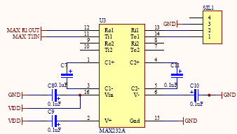
    Interface série (UART 0V / 5V) vers RS232 (9V / -9V).

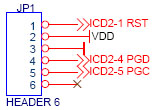
    Connectique pour le programmateur / debugger ICD2.


    Interface du dsPIC 30F3010


    Under construction (28/03/2007) revenez plus tard...


    Download executable and sources.

    Download :
    tp0.zip   Sources C de l'exemple TP0.
    tp1.zip   Sources C de l'exemple TP1.
    L6234.pdf   Datasheet de l'onduleur triphasé L6234.
    mrvlin_sch.pdf   Schéma du circuit électronique MRVlin.


    Back to homepage

    Last update : 28/03/2007